FemtoScan Online
Scanning Probe Microscope
Technical description
Purpose of "FemtoScan Online" scanning probe microscope is to observe surface morphology and to measure local properties of samples with the sub-nanometer spatial resolution on air and in liquids. Principle of operation is based on detection of a probe over a surface movement and simultaneous probe-sample interaction measurement.
Scanning mode name is defined by a signal that is chosen to measure probe-sample interaction. In atomic-force mode measured interaction is repulsion force between atoms of probe and atoms of a sample. In tunneling mode this signal is tunneling current between a probe and a sample. High resolution is obtained by using special probes with very sharp tip. "FemtoScan Online" scanning probe microscope is a first in the world microscope in which remote control, data acquiring and analysis functions are realized. Thus overall microscope control can be done even through Internet. This microscope allows performing all kind of measurements from any computer connected to local network or Internet. Unlimited number of authorized users can connect to the microscope and get access to all data obtained in experiment in real-time manner, as well as they can carry out data processing and get 3-dimentional images of studied objects. The microscope allows carrying out measurements on air and in liquid media. It is designed to use in fundamental and applied research, as well as to use in distant learning programs for education in practical nanotechnology.
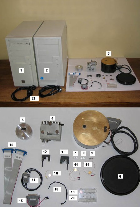
Microscope set-up consists from number of main and minor units, parts, and connectors according to Package Contents (see Appendix 1). Microscope set-up is represented on pic. 1. Control Unit 1 is connected to Converters unit 2 by "Control Unit - Converters Unit" cable 16. Units 1 and 2 are connected to power supply line with Power cable 21. Control Unit is made on basis of personal computer working under Microsoft™ Windows XP operating system.
Software, installed on Control Unit listed below:
1) "FemtoScan Online" scanning probe microscope control and image processing software (Computer software registration certificate #2002612063).
2) OpenOffice.org software package (distributed free, see www.openoffice.org for further details).
3) Adobe Acrobat Reader software (distributed free, see www.adobe.com for further details).
Converters Unit is connected to Piezomanipulator Unit 3. Unit 3 built-in cable is used to connect it to Unit 2. High-precision positioning element made of piezoceramic material is installed inside Unit 3. Coarse positioning along vertical axis is preformed by stepper motor installed inside Unit 3. Magnetic holder is mounted in face of positioning element. Antivibration pedestal 6 is used to isolate microscope from vibration. Scanning heads that are placed on top of Unit 3 are used to perform scanning in different modes.
Moving a head by hand can perform coarse positioning along horizontal axis. It is recommended to use short-focus microscope-monocular with 20x magnification to increase positioning accuracy. For best results it is good to have this optical microscope-monocular installed on the long tripod and to have sample illumination. When coarse positioning is done monocular should be removed and illumination should be turned off.
STM Head 5 and STM Stage 10 are used to work in STM (Scanning Tunneling Microscopy) mode of operation. Head 5 is connected with Unit 3 by built-in cable, Stage 10 is connected to single lead of the same built-in cable. A metallic wire 0.1 mm in diameter is placed in holder of the STM head. It is recommended to cut the end of this wire using clear and sharp scissors.
RAFM Head 4 is used to operate in AFM (Atomic-Force Microscopy) and RAFM (Resonance Atomic-Force Microscopy) modes. Head 4 is connected with Unit 3 by built-in cable. It is needed to connect RAFM Head 4 with Converters Unit by a "RAFM" Cable 17 for operation in RAFM mode. RAFM cantilever holder 12 is used for operation in AFM and RAFM modes in air. Depending on sample height one stage from Stage h3 7, Stage h4 8, and Stage h5 9 can be chosen to mount a sample. It is recommended to mount a sample using double-sided adhesive tape. It is recommended to put a stage with a sample on a magnetic holder of the microscope using non-magnetic tweezers.
AFM probes 19 with different rigidity are used for scanning in AFM mode. RAFM probes 20 with different rigidity are used for scanning in RAFM mode. To mount a probe (cantilever) into RAFM cantilever holder 12, you should flip-over the holder and push on it, then put a cantilever under a springy slat, then release the holder. It is recommended to mount an AFM probe using non-magnetic tweezers with thin ends.
Stage with thermostatic regulator 14 is used for scanning with thermostating in air. Cable "Thermostat" 15 is used to connect the stage to the Converters Unit.
To perform scanning with resistivity measurements cantilever holder 12 is connected with head 4 by "Resistivity mode" cable 18. In this case stage 10 is used and single lead of the stage is connected to single lead of the cable 18.
To perform scanning in liquid (with optional thermostating) liquid cell RAFM cantilever holder 13, liquid cell with thermostatic regulator 11 and Cable "Thermostat" 15 are used. It is recommended to compensate liquid evaporation by adding necessary amount of liquid using 2,5 ml syringe with thin needle. To mount a cantilever into holder 13, flip-over the holder and push on it, then put a cantilever under a wire bridge, then release the holder.
|